The Projection window shows various map projections of the events. Each projection translates the theta/phi for the hits into a different coordinate system. The hit angles can be relative to the detector fixed frame, or relative to the current fit if one is available. The reference frame is selected in the View menu of this window.
The PMT hits are displayed in the same color scheme as hits in the other windows. The size of the hits may be configured to represent additional information depending on the settings in the Hits menu. By default the hits are fixed size, but this may be changed to make the size relative to Qhs. In this mode, the hit size is proportional to the absolute value of the difference between the raw Qhs value and a fixed pedestal of 500, so hits with Qhs near 500 are small and very high or low charge hits appear large in the display. The hit size may also be made proportional to the solid area subtended by the PMT (accounting for the distance to the PMT, but not the cosine of the angle). The solid-angle option is useful only when displaying the hit coordinates relative to a fit.
The bottom and right scrollbars rotate the event with respect to the displayed grid. The left scrollbar sets the magnification for zooming in/out. The whole image can be shifted by grabbing and dragging with the mouse. To return the display to it's original orientation and size, select Move/To Home from the menu.
All projections are views from the outside of the sphere. Grid lines show increments of 30 degrees in latitude and longitude. In the home position, the center of all projections (except polar projections) is oriented with the z axis upwards, the y axis to the right, and the x axis out of the screen. This is the same orientation as the main 3-D display in the home position. For polar projections, the center of the projection is looking down along the z axis, with the y axis to the right, and the x axis downwards. For dual projections, the left side is the front, and the right side is the back (except for polar projections, where the left is top, and the right is bottom).
Here is a brief description of the available projection types available
through the Projection menu:
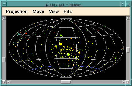
Rectangular Lines of longitude and latitude are straight and equally spaced. This projection does not preserve area. Cylindrical Lambert Like the Rectangular projection but lines of latitude are spaced to give an equal-area projection. Sinusoidal Lines of longitude are sinusoids, and lines of latitude are equally spaced. This projection preserves area. Elliptical Linear Lines of longitude are ellipses, and lines of latitude are parallel and equally spaced. This projection does not preserve area. Elliptical Mollweide Similar to Elliptical Linear except that lines of latitude are spaced according to Mollweide's projection which preserves area. Elliptical Hammer Hammer's equal area projection, where lines of latitude are curved. This is a good projection to minimize shape distortion while preserving area. Extended Hammer Allows events which cross the poles to be viewed without interruption, at the expense of greater distortion near the plot edges. This projection preserves area. Polar Linear This projection looks down on the detector, with lines of longitude radiating outwards from the center, and lines of latitude equally spaced. It is a useful projection when displaying hit coordinates relative to a fit, but does not preserve area. Polar Equal Area A polar projection where the lines of latitude are spaced to preserve area. It is equivalent to the Extended Hammer projection except that the projection is circular and centered on the Z axis instead of the X axis. "Dual" Projections Most of the above projection types also have corresponding "dual" projection options. The dual projection splits the SNO sphere into two halves, with the front/top half on the left and the right/bottom half on the right.